Hydraulics and Pneumatics: Unit V: Trouble Shooting and Applications
Appendix - troubleshooting and applications
Trouble Shooting and Applications - Hydraulics and Pneumatics
Mobile hydraulic systems are used, for example, in construction, agricultural and forestry machinery.
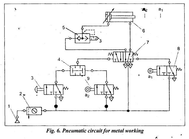
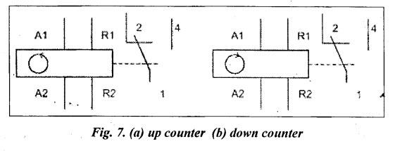
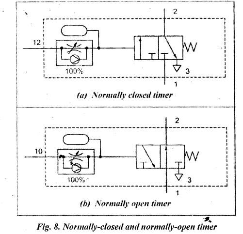
UNIT V TROUBLESHOOTING AND APPLICATIONS • Mobile hydraulic systems are used, for example, in construction, agricultural and forestry machinery. Where high output power combined with minimum weight is required, this form of power is particularly effective, thanks to the exceptionally high- power density of hydraulic systems combined with low space requirements. • The need/demand for mobile hydraulics is constantly increasing due to the following parameters: (i) extreme pressures (ii) demanding temperature profiles (iii) increasingly compact designs (iv) increasingly globally defined operating conditions (v) lowest failure rates (vi) longer service lives (vii) stricter emissions standards • This topic is a part of Chapter 16, and can be studied after Section 16.9. Functional and Operational Requirements It is widely used in the sheet metal processing industry. At present, the bending machine mostly adopts a hydraulic system. Although the hydraulic system can achieve higher pressure and the transmission is relatively stable, the leakage problem of the hydraulic system cannot be ignored, which is easy to cause environmental pollution, and the hydraulic system is difficult to troubleshoot, and the maintenance personnel is required to compare. high. Relatively speaking, the pneumatic system is air-free, has no cost, and does not cause pollution when discharged into the atmosphere. Moreover, the maintenance is simple and convenient, the pipeline is not easy to be blocked, the use is safe and reliable, and the automatic overload protection can be realized. It is more and more widely used in mechanical manufacturing. In the field of pneumatics, an electric counter consists of a coil, associated circuits and contacts, a reset coil, manual reset, release button and a display window. Pressure the release button of the counter and entering the deşired count valve set the pre-determining counter. The pre-determined count valve is displayed in the window. There are two types of counters: 1. Up counter, and 2. Down counter 1. Up counter: An up counter counts electrical signal upwards from zero. For each electrical counting pulse input to an up-counter coil, the counter value is incremented by 1. When the predetermined valve has been reached, the relay picks up and the contact set is actuated. 2. Down counter: A down counter counts electrical signal downwards from preset valve. If the count valves of zero is reached the relay picks up and the contact set is actuated. The counter can be reset manually by pressing the reset button or electrically by applying a reset pulse to the reset coil. The pre-determined value is maintained when the counter is reset. The symbols of up counter and down counter is shown in Fig.7(a) and (b). Pneumatic timers are used to create time delay of signals in pilot operated circuits. They are available as Normally Closed (NC) Timers and Normally Open (NO) timers (Fig. 8). Usually, pneumatic timers are On Delay Timers Delay of signals is very commonly experienced in applications such as bonding of two pieces. Normally Open pneumatic timer are also used in signal elimination. Normally Open Pneumatic Timers are used as a safety device in 'Two Hand Blocks'. A pneumatic timer is a combination valve that consists of three parts: (a) 3/2 way pilot operated directional control valve [NC or NO]; (b) an one way flow control valve, and (c) an accumulator. • The Internet of Things (IoT) is now supporting a number of industrial technologies, the most recent of which are fluid power management and control systems. By offering more intelligent and effective monitoring tools and controls, IoT is transforming the hydraulics and pneumatics industries. Complex systems can be created, launched, and monitored via the cloud with the aid of IoT. Even remote management of those operations is conceivable. • Intelligent algorithmic systems that are powered by artificial intelligence (AI) or machine learning, as opposed to IT staff sitting at a desk, can monitor everything. • loT for hydraulics and pneumatics must be integrated in a safe, efficient manner, just like any other piece of machinery in production or elsewhere. • Due to the remote opportunities it provides, technology has enormous promise. For instance, a solenoid valve outfitted with an IoT control and sensor device can be remotely managed, watched over, and activated. • Industrial operations and manufacturers using pneumatics have access to more IIoT. technology than ever before, from position sensors on cylinders to system flow sensors and smart edge gateways that operate independently from the machine controller with globally accepted communication protocols. Applications of lot in Fluid Power Systems Some of the fields where IoT can serve in the field of fluid-operated systems are given below: 1. Improving safety to protect people and equipment Consider a machine that employs a safety light curtain to shut off its pneumatic valves whenever a worker loads or unloads a component for processing. Historically, safety applications have used statistical calculations to determine the mission time replacement cycle of a safety component. In order to maintain the accuracy of the computed statistical safety function, the term "mission time" refers to the number of cycles after which a safety component must be replaced, whether it is operational or not. There are additional measurable aspects that may not be taken into account, even though the valve may appear to be fine based on its rated mission time (for example, changes in valve response time). 2. Improving predictive and preventative maintenance Any production environment faces daily challenges in dealing with wear and tear. To optimise machine life cycles and increase overall equipment effectiveness, predictive and preventative maintenance procedures are essential (OEE). For example, maintenance technicians can analyze appropriate data from IIoT sensors. By detecting a millisecond rise in the stroke speed of an actuator, they may utilise that information to forecast that a shock absorber at the end of the actuator is degrading. Predictive maintenance procedures may be triggered in order to replace the worn shock absorber. As a result, there are fewer complete or undetected failures, shorter or fewer machine stoppages, and decreased unplanned downtime. Any production environment faces daily challenges in dealing with wear and tear. To optimise machine life cycles and increase overall equipment effectiveness, predictive and ̧ preventative maintenance procedures are essential. 3. Regulating upstream/downstream flow In especially for upstream/downstream flow, combining the traditional advantages of a pneumatics system with IIoT-based technologies helps maximise process control and monitoring. Enhanced OEE is the outcome. Consider a facility that uses a system where the gates on a hopper or silo that dispenses bulk materials for packaging can only be in the fully open or fully closed positions when they are pneumatically activated. Downstream processing stations may be flooded or starved by uneven product flow and traffic congestion. Inefficiencies and bottlenecks develop throughout the plant as a result of the inability to adjust the position of the dispensing gates in response to downstream demand. The results can include harm to the bulk material or paying employees overtime wages to meet production requirements. This can be enhanced by loT systems. Each gate's position can change from 0 to 100% of the opening using an intelligent, IIoT-based closed-loop system with the proper sensors on IIoT-enabled pneumatics components instead of only being in the open or closed position. Without changing the controller program, the flexibility allows for significantly better flow management of bulk materials. 4. Organizing data with a Smart Pneumatics Monitor More data points are being produced across the manufacturing systems where pneumatics technology is deployed as it develops into an intelligent technology. Diagnostic data, utilisation statistics, and lifetime data are a few examples. Additionally, the machine control network could become overloaded with performance data from all the pneumatics components, along with other intelligent machine drives, devices, and subsystems, which would complicate the automation process and control performance.MOBILE HYDRAULICS
PNEUMATIC CIRCUIT FOR METAL WORKING SHEET METAL BENDING***
COUNTER CIRCUITS
TIMER CIRCUITS
IoT IN HYDRAULICS AND PNEUMATICS
Hydraulics and Pneumatics: Unit V: Trouble Shooting and Applications : Tag: : Trouble Shooting and Applications - Hydraulics and Pneumatics - Appendix - troubleshooting and applications
Related Topics
Related Subjects

Hydraulics and Pneumatics
ME3492 4th semester Mechanical Dept | 2021 Regulation | 4th Semester Mechanical Dept 2021 Regulation