Hydraulics and Pneumatics: Unit V: Trouble Shooting and Applications
Appendix - pneumatic and electro-pneumatic systems
Trouble Shooting and Applications - Hydraulics and Pneumatics
A full pneumatic circuit is used in various industrial settings to perform a number of functions.
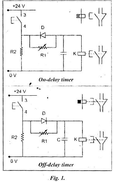
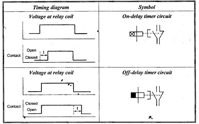
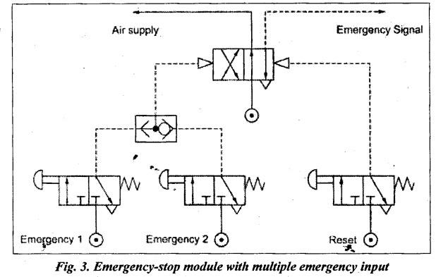
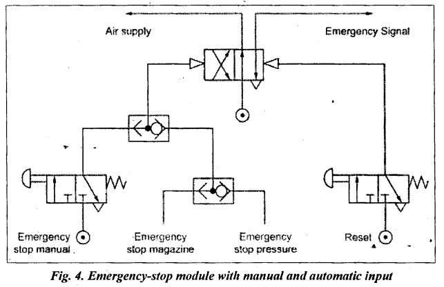
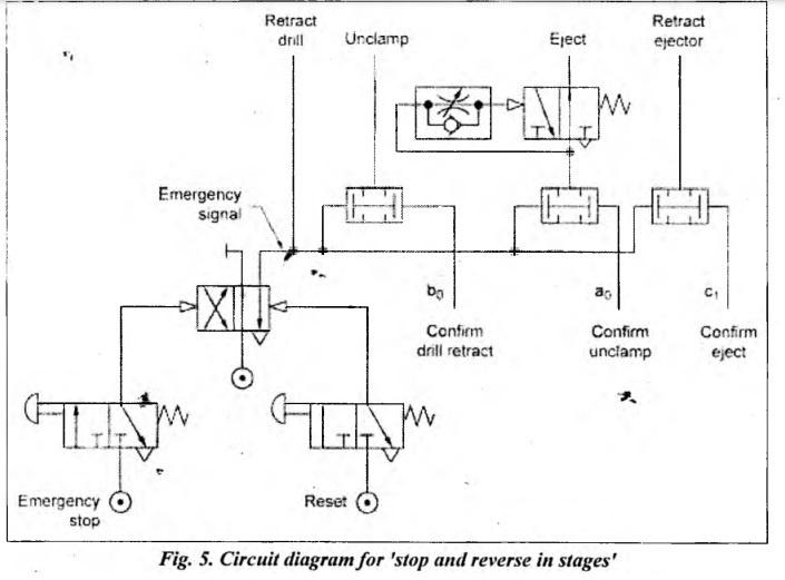
APPENDIX UNIT IV PNEUMATIC AND ELECTRO-PNEUMATIC SYSTEMS • A full pneumatic circuit is used in various industrial settings to perform a number of functions. Many sectors, including the automotive, culinary, chemical, and so forth, must employ a comprehensive pneumatic system due to the dangerous environment on the site and limitations on the use of power in the system. • Cascade refers to a series. This method makes use of a variety of signalling components to control the sequence of pneumatic cylinders. These signalling components are propelled by the forward and backward cylinder strokes, while a cascade system provides the air supply to the pilot line. • Automation requires the sequencing of operations because it frequently encounters control circumstances that call for output sequences, with sensors regulating the changeover from one output to another. 1.1. Cascade Method of Pneumatic Circuit Design: Refer to Section 13.12.1, Chapter 13. 1.2. Procedure for Cascading Pneumatic Circuits: Refer to Section 13.12.1.1, Chapter 13. 1.3. Advantages of Cascade Method: Refer to Section 13.12.1.2, Chapter 13. 1.4. Industrial Applications / Problems of Pneumatics Circuits Design using Cascade Method: Refer to Examples 13.1 to 13.9, Chapter 13. • This topic is a part of Chapter 13, Unit 4, and can be studied after Section 13.11. • Timers are required in control systems to effect time delay between work operations. This is possible by delaying the operation of the associated control element through a timer. Most of the timers we use are electronic timers. • "This topic is a part of Chapter 14, Unit 4, and can be studied after Section 14.9. • There are two types of time relay: (i) Pull in delay (on-delay timer); and (ii) Drop-out delay (off-delay timer). (i) On-delay Timer: In the on-delay timer, shown in Fig. 1(a), when the push button is pressed (ON), capacitor C is charged through potentiometer R1 as diode D is reverse-biased. The time taken to charge the capacitor depends on the resistance of the potentiometer (R1) and the capacitance (C) of the capacitor. By adjusting the resistance of the potentiometer, the required time delay can be set. When the capacitor is charged sufficiently, coil K is energised, and its contacts are operated after the set time delay. When the push button is released (OFF), the capacitor discharges quickly through a small resistance (R2) as the diode bypasses resistor R1, and the contacts of relay (K) return to their normal position without any delay. (ii) Off-Delay Timer: In the off-delay timer (Fig. 1(b)), the contacts are operated without any delay when the push button is pressed (ON). The contacts return to the normal position after the set delay when the push button is released (OFF). Symbol: The timing diagrams and symbols of the on-delay and off-relay timers are given in Table 1. Table 1. Timing diagram for on- and off-delay timer Almost all industrial machine controls consist of sequential circuits and one or two fringe condition modules. The most commonly encountered modules are: (i) the cycle selection module, (ii) the emergency-stop module, and (iii) the two-hand start module. Now we shall discuss the emergency-stop module. EMERGENCY STOP MODULE A. BASIC EMERGENCY-STOP MODULE The majority of automated machines operate according to a programmed sequence. Due to mishaps such as damaged tooling, a misaligned workpiece in an assembly line, an empty workpiece magazine, a sudden drop in supply pressure or an endangered operator, the sequence must be interrupted or the start of a new cycle prevented if automatic cycling was selected. The nature of such an interruption varies with the anticipated degree of damage and the inherent safety equipment built into the machine (safety guards, remote operation, etc.). The distinction is basically between the following emergency stop conditions: (2) stop at end of the commenced step (3) stop instantaneously (4) stop and reverse in stages (5) stop and reverse circuit to end-of-cycle condition. (6) reverse cylinders that are in motion It is the circuit designer's responsibility to decide which action the cylinders must take when an emergency stop is signalled and the correct choice on the circuit designer' part can prevent serious harm to operators or avoid costly damage to workpieces, tooling, and machinery. For maximum operator and machine safety, all emergency signals should be stored in a memory-type valve. It is recommended that the emergency-reset valve be placed inside the control cabinet or, if this is not possible, that a key-operated valve is used, which is only accessible to authorised personnel. To avoid directional control valve blockage due to opposing signals stemming from position sequence valves, all such valves must be air supplied through the emergency-stop memory, as shown in Fig.2. When the memory is selected into the emergency position, the air supply to the aforementioned valves is stopped, and D.C.V. blockage is prevented. Detent-type push-button emergency valves are commonly used but have an inherent danger: the valve can simply be reset by operators unaware of an emergency situation, which could lead to machine damage or, more seriously, cause harm to the operator himself. B. EMERGENCY-STOP MODULE WITH MULTIPLE EMERGENCY INPUT Where machinery is operated from several locations, it is imperative to provide emergency-stop valves for all such locations. Large machines or installations where operators and personnel are exposed to dangers should be provided with ample emergency-stop provisions, and each stop valve must be attached to an independent air supply, as in Fig.3. C. EMERGENCY-STOP MODULE WITH MANUAL AND AUTOMATIC INPUT Where the emergency signal must be triggered either by an operator or by an external machine operation, such as 'pressure inadequate', 'magazine empty', or similar stop- demanding signals, the emergency-stop module shown in Fig.4 is used. D. 'STOP AND REVERSE IN STAGES' EMERGENCY-STOP MODULE INTEGRATION A special case of integration of fringe integrated emergency stop module is taken, which is 'stop and reverse in stages'. It is applicable where a machine cycle after emergency interruption must be reversed to a safe condition (interim condition) or to the end-of-cycle condition, but the reversal has to occur according to a predetermined 'safety sequence'. For example, in a clamp-drill-unclamp sequence, the simultaneous retraction of the drill cylinder with the unclamping action of the clamp cylinder could cause grave dangers to the operator, workpiece, and tooling, since the drill could still be inside the workpiece while unclamping occurs, thus causing the workpiece to be ripped out of the clamping device and hurled out of the machine. The 'stop and reverse in stages' emergency-stop module integration into a three-cylinder circuit is shown in Fig.5. The sequence for these cylinders is as follows A1-B1-B0-A0-C1-C0 (six sequence steps). Cylinder A is used for clamping, cylinder B operates the drill feed and cylinder C ejects the workpiece. The safety sequence for emergency-reverse must be: retract drill-unclamp eject workpiece as seen in Fig.5.1. CASCADE METHOD
2. ELECTRO-PNEUMATIC CIRCUITS - TIMERS**
3. INTEGRATION OF FRINGE CIRCUITS
(1) stop at end of cycle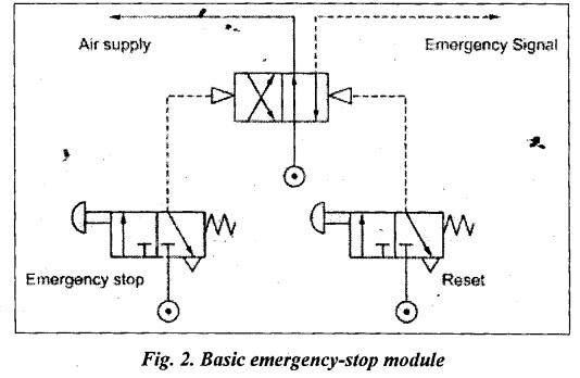
Hydraulics and Pneumatics: Unit V: Trouble Shooting and Applications : Tag: : Trouble Shooting and Applications - Hydraulics and Pneumatics - Appendix - pneumatic and electro-pneumatic systems
Related Topics
Related Subjects

Hydraulics and Pneumatics
ME3492 4th semester Mechanical Dept | 2021 Regulation | 4th Semester Mechanical Dept 2021 Regulation