Strength of Materials: Model Questions Papers
Anna university solved question papers
Thin Cylinders, Spheres and Thick Cylinders - Strength of Materials
Anna university solved question papers:Strength of Materials: Unit V: Thin Cylinders, Spheres and Thick Cylinders : MAY/JUNE 2006
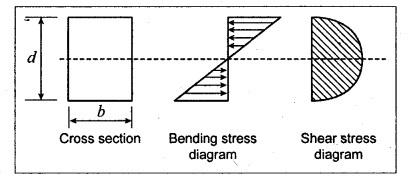
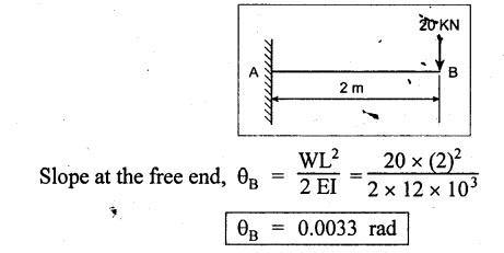
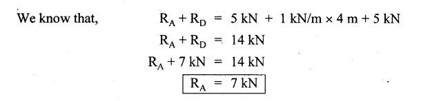
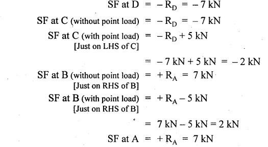
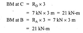
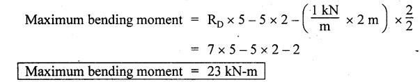
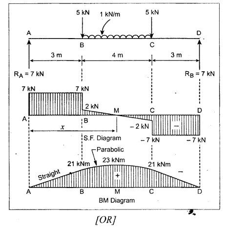
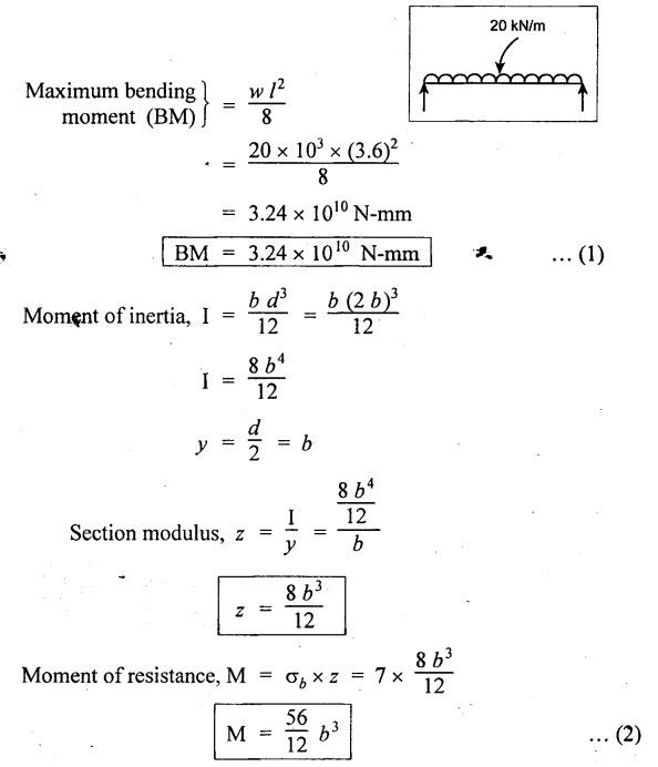
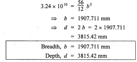
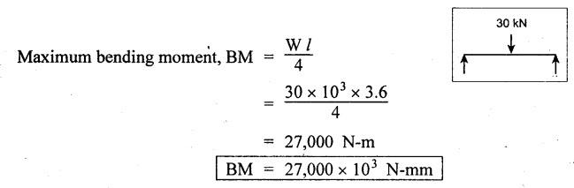
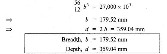
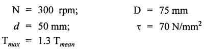
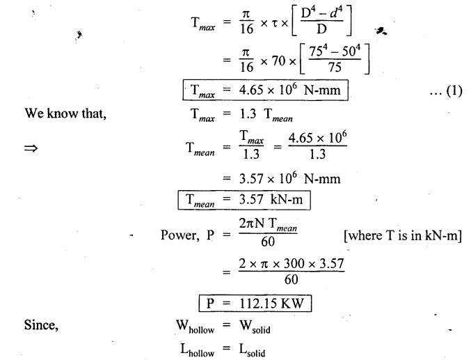
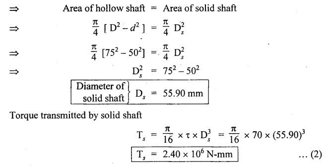
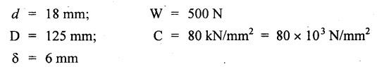
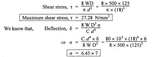
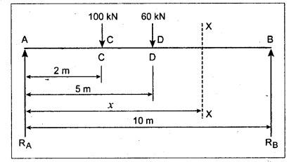
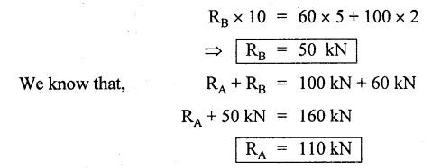
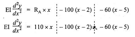
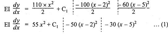
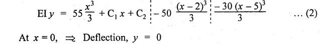
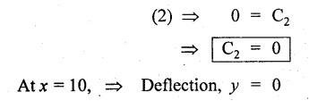
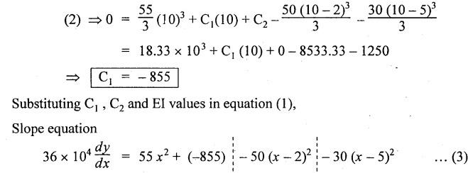
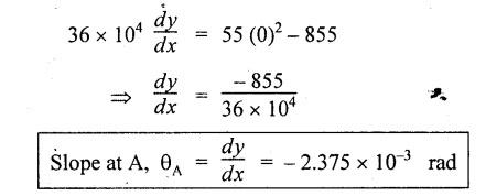
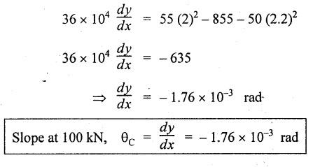
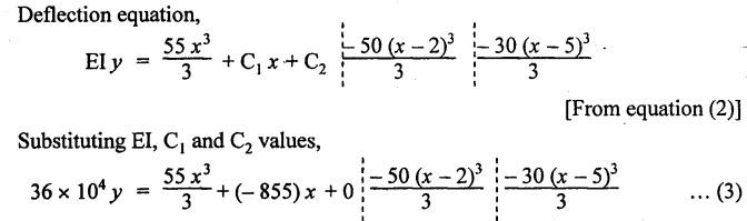
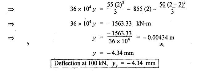
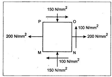
ANNA UNIVERSITY SOLVED QUESTION PAPERS B.E/B.TECH DEGREE EXAMINATION, MAY/JUNE 2006 Fourth Semester (Mech) CE1262 STRENGTH OF MATERIALS (Revised Syllabus - Regulation 2004) Time: Three hours Answer ALL Questions. Maximum: 100 Marks Part A (10 × 2 = 20 marks) 1. A circular rod 2 m long and 15 mm diameter is subjected to an axial tensile load of 30 kN. Find the elongation of the rod if the modulus of elasticity of the material of the rod is 120 kN/mm2. Ans. Refer Page no. 1.6, Example 1.1. 2. Define strain energy and write its unit. Ans. Refer Page no. 4.103, Section 4.2. 3. A cantilever beam of 3 m long carries a load of 20 kN at its free end. Calculate the shear force and bending moment at a section 2 m from the free end. Shear force is 20 kN. Bending moment is 20 × 2 = 40 kN-m 4. Sketch (a) the bending stress distribution, (b) shear stress distribution for a beam of rectangular cross section. 5. Find the torque which a shaft of 50 mm diameter can transmit safely, if the allowable shear stress is 75 N/mm2. Ans. Refer Page no. 3.9, Example 3.1. 6. Differentiate open coiled helical spring from the close coiled helical spring and state the type of stress induced in each spring due to an axial load. Ans. Refer Page no. 3.141, Question no. 5. Refer Page no. 3.142, Question no. 10 and 11. 7. A cantilever beam of spring 2 m is carrying a point load of 20 kN at its free end. Calculate the slope at the free end. Assume EI = 12 × 103 kN-m2. 8. Calculate the effective length of a long column, whose actual length is 4 m, when (a) Both ends are fixed. (b) One end is fixed while the other end is free. NOT IN SYLLABUS 9. The principal stress at a point are 100 N/mm2 (tensile) and 50 N/mm2 (compressive) respectively. Calculate the maximum shear stress at this point. Ans. 10. A spherical shell of 1 m diameter is subjected to an internal pressure 0.5 N/mm2. Find the thickness if the allowable stress in the material of the shell is 75 N/mm2. Ans. Refer Page no. 5.21, Example 5.14. We know that, SF Calculations: Bending Moment Calculation: Bending moment at D = 0 BM at A = 0 The maximum bending moment is situated at a distance of x from the point A, where the shear force changes its sign. x = 3m + 2 m = 5 m Maximum Bending Moment: Taking moment about the point where the SF is zero (at x = 5 m) SF and BM diagram: 12. (b) A timber beam of rectangular section is to support a load of 20 kN uniformly distributed over a span of 3.6 m, when the beam is simply supported. If the depth of the section is to be twice the breadth and the stress in the timber is not exceed 7 N/mm2, find the breadth and depth of the cross section. How will you modify the cross-section of the beam, if it carries a concentrated load of 30 kN placed at the mid-span with the same ratio of breadth to depth. Ans. Refer Page no. 2.150, Example 2.59. Given: Load, w = 20 kN = 20 × 103 N Length, l = 3.6 m Maximum stress, σb = 7 N/mm2 Point load, wp = 30 kN = 30 × 103 N Depth, d = 2b (Breadth) To find: Case (i): Uniformly distributed load, 20 kN (i) Breadth, b (ii) Depth, d Case (ii): Point load 30 kN (i) Breadth, b (ii) Depth, d Solution: Case (i): Simply supported beam carried a uniformly distributed load. Equating the moment of resistance to maximum bending moment Case (ii): Beam carries a point load at the centre. Equating the moment of resistance to maximum bending monent Result: Case (i): For uniformly distributed load, 20 kN Breadth, b = 1907.711 mm Depth, d = 3815.42 mm Case (ii): For point load, 30 kN Breadth, b = 179.52 mm Depth, d = 359.04 mm 13. (a) Calculate the power that can be transmitted at a 300 rpm by a hollow steel shaft of 75 mm external diameter and 50 mm internal diameter when the permissible shear stress for the steel is 70 N/mm2 and the maximum torque is 1.3 times the mean. Compare the strength of this hollow shaft with that of an solid shaft. The same material, weight and length of both the shafts are the same. Given: To find: 1. Power. 2. Strength of hollow shaft. 3. Strength of solid shaft. Solution: We know that, Maximum torque for hollow shaft [considering shear stress] (Material)hollow = (Material)solid From equation (1) and (2), we know that, Result: 1. Power, P = 112.15 KW 2. Strength of hollow shaft, Th = 4.65 × 10⁶ N-mm 3. Strength of solid shaft, Ts = 2.40 × 10⁶ N-mm 4. Comparison, Th = 1.937 Ts [OR] 13. (b) A helical spring of circular cross section wire 18 mm in diameter is loaded by a force of 500 N. The mean coil diameter of the spring is 125 mm. The modulus of rigidity is 80 kN/mm2. Determine the maximum shear stress in the material of the spring. What number of coils must the spring have for its deflection to be 6 mm ? Given: To find: 1. Maximum shear stress, τ. 2. Number of coils, n. Solution: We know that, Result: 1. τ = 27.28 N/mm2 2. n = 7 14. (a) A beam is simply supported as its ends over a span of 10 m and carries two concentrated loads of 100 kN and 60 kN at a distance of 2 m and 5 m respectively from the left support. Calculate (i) slope at the left support; (ii) slope and deflection under the 100 kN load. Assume EI 36 × 104 kN-m2. Given: EI = 36 × 104 kN-m2 To find: 1. Slope at the left support. 2. Slope and deflection under 100 kN load. Solution: Macualay's Method: Let RA and RB be the reaction at the left and right supports. Taking moments about A, Taking bending moment at x: Integrating we get, Integrating again, we get Substituting x = 0, y = 0 values in equation (2) upto first dotted line. Substituting x = 10, y = 0 values in equation (2), (i) Slope at the left support: Slope at the left support, i.e., at A, x = 0. Substituting x = 0 in equation (3) upto first dotted line. (ii) Slope at 100 kN load: Substituting x = 2 m in equation (3) upto second dotted line. (iii) Deflection at 100 kN: We know that, Deflection at 100 kN, substituting x = 2 m in equation (3) upto second dotted line. Result: 14. (b) Find the Euler critical load for a hollow cylindrical cast iron column 150 mm external diameter, 20 mm wall thickness if it is 6 m long with hinged at both ends. Assume Young's modulus of cast iron as 80 kN/mm2. Compare this load with that given by Rankine formula. Using Rankine constants a = 1/1600 and 567 N/mm2. NOT IN SYLLABUS 15. (a) A steel cylinder shell 3 m long which is closed at its ends, had an internal diameter of 1.5 m and a wall thickness of 20 mm. Calculate the circumferential and longitudiṇal stress induced and also the change in dimensions of the shell if it is subjected to an internal pressure of 1.0 N/mm2. Assume the modulus of elasticity and Poisson's ratio for steel as 200 kN/mm2 and 0.3 respectively. Ans. Refer Page no. 5.16, Example 5.10. [OR] 15. (b) The state of stress at a certain point in a strained material is shown in Fig.1. Calculate (i) Principal stress, (ii) Inclination of the principal planes, (iii) Normal, shear and resultant stress on the plane MN. Ans. Refer Page no. 1.179, Example 1.78.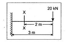


Strength of Materials: Model Questions Papers : Tag: : Thin Cylinders, Spheres and Thick Cylinders - Strength of Materials - Anna university solved question papers
Related Topics
Related Subjects
Strength of Materials
CE3491 4th semester Mechanical Dept | 2021 Regulation | 4th Semester Mechanical Dept 2021 Regulation