Theory of Machines: Unit I: Kinematics of Mechanisms
Acceleration in four-bar mechanism
Kinematics of Mechanisms - Theory of Machines
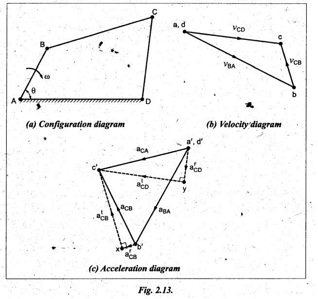
Fig.2.13(a) snows a four-bar chain ABCD in which AD is fixed and BC is the coupler.
ACCELERATION IN FOUR-BAR MECHANISM
Fig.2.13(a)
snows a four-bar chain ABCD in which AD is fixed and BC is the coupler. AB is
the driver rotating at an angular speed of o rad/s in the clockwise direction.
It is required to draw the acceleration diagram of the configuration.
Procedure:
Step 1: Configuration
diagram: First of all, draw the configuration
diagram, to some suitable scale, as shown in Fig.2.13(a).
Step 2: Velocity of
input link: When length of input link AB and its
angular velocity ωAB are known, then the velocity of input link
(ie., crank AB) is given by

Step 3: Velocity
diagram: Now draw the velocity diagram, as
shown in Fig.2.13(b), using the procedure given in Section 2.6.
Step 4: Velocity of
various links:
By
measurement from the velocity diagram, we get vCB = vector bc;
and vCD = vector dc.
The
angular velocities of links BC and CD can be determined by using the relations
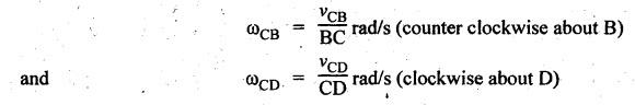
Step 5: Construction
of acceleration diagram:
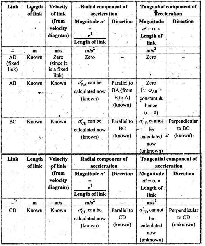
Using
the velocity of various links that are obtained with the help of velocity
diagram, the values of radial and tangential components of acceleration of
various links can be calculated as shown in Table 2.2 below.
Table 2.2. Radial and tangential components of acceleration of
various links
Now
using the known values of magnitude and direction of acceleration components,
the acceleration diagram can be constructed, as shown in Fig.2.13(c), to some
suitable scale, using the procedure given below.
1.
Since the link AD is fixed, therefore take a' and d' as one
point.
2.
From point a', draw vector a'b' such that a'b' = arBA
= v2BA/AB in the direction parallel to BA to
represent the radial component of acceleration of link AB (ie., arBA).
Since atBA = 0, therefore aBA = arBA
3.
From point b', draw vector b'x such that b'x = arCB
= v2CB / BC in the direction parallel to CB to represent
the radial component of acceleration of link BC (i.e., arCB).
Now from point x, draw vector xc' perpendicular to BC to
represent the tangential component of acceleration of link BC (ie., atCB)
whose magnitude is unknown.
4.
From point d', draw vector d'y such that d'y = drCD/DC
in the direction parallel to CD to represent the radial component of
acceleration of link CD (i.e., drCD). Now
from point y, draw vector yc' perpendicular to CD to represent
the tangential component of acceleration of link (i.e., dtCD)
whose magnitude is unknown.
5.
The vectors xc' and yc' intersect at c'. Join a'c'
and b'c'.
Step 6: Acceleration
of various links:
Now
by measurement from the acceleration diagram, the various components of
acceleration of links can be found.
Acceleration
of crank AB = aBA = arBA =
vector a'b'
Radial
component of acceleration of link BC = arBC = vector
b'x
Tangential
component of acceleration of link BC = atBC = vector
xc'
Total
acceleration of link BC = aBC = vector b'c'
Radial
component of acceleration of link CD = arCD =
vector a'y
Tangential
component of acceleration of link CD = atCD = vector
yc'
Total
acceleration of link CD = aCD = vector a'c'
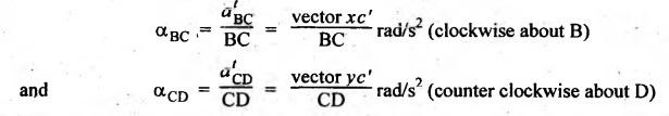
Also
the angular accelerations of links BC and CD can be determined as
Theory of Machines: Unit I: Kinematics of Mechanisms : Tag: : Kinematics of Mechanisms - Theory of Machines - Acceleration in four-bar mechanism
Related Topics
Related Subjects

Theory of Machines
ME3491 4th semester Mechanical Dept | 2021 Regulation | 4th Semester Mechanical Dept 2021 Regulation